Get more functionality by logging in. If you don't have an account register here
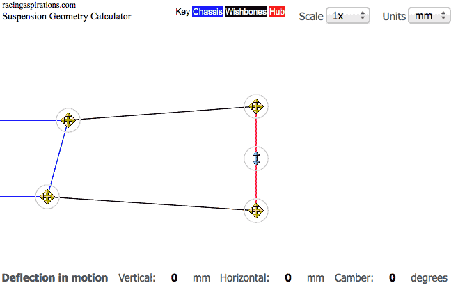
Settings (drag the icons to change pickup points)
Camber degrees
Upper wishbone length mm
Upper wishbone angle degrees
Lower wishbone length mm
Lower wishbone angle degrees
Distance between mounting points on hub mm
Distance between mounting points on chassis mm
SAL (distance between the intersection of wishbones and the hub) mm
Description
The classic version of the suspension geometry calculator. It is simplicity itself and a great place to start learning about suspension geometry. With this calculator you will see how bump and droop can affect camber.
 
Sharing
Tags
 

Comments (2)

Avatar photo
Racing Aspirations February 23, 2016 at 4:25 pm

Try the new calculator – http://www.racingaspirations.com/apps/suspension-geometry-calculator
CLick on the pencil icon, then the form icon and you will be able to enter the dimensions direct

NickPPJr February 23, 2016 at 4:22 pm

I am attempting to utilize your calculator and am puzzled as to where to edit dimensions. Any help is appreciated. I want to do a comparison of a stock 1955 Chevy versus a C4 Corvette (1997) to visually see the difference. Any help will be appreciated. Below are the dimensions I have so far. Stock Tri5 suspension measurements:

Lower a-arm pivot spacing 20.5″
Lower a-arm length 14.75″
Spindle height (balljoint centers) 9.75″
SAI 3.5 degrees
Vertical spacing between upper and lower a-arm shafts, 10.25″ (average at center of shaft)
Upper a-arm length 10.25″
Lower balljoint center to spindle center 2.813″ (vertically)
Wheel mounting surface to lower balljoint center 4.875″(horizontally)
6.70-15 tire rolling radius 13.36″
Stock wheel offset +0.56″

225/60-15 tire rolling radius 12.40″ (BFG)Assumed modified wheel offset +.5″ (7″ width)
255/45-17 tire rolling radius 12.67″ (Kumho)

Early C4 suspension measurements

Lower a-arm pivot spacing 24.125″
Lower a-arm length 13.25″
Spindle height (balljoint centers) 11.875″
SAI 8.744 degrees
Vertical spacing between upper and lower a-arm shafts, 10.84″ (average at center of shaft)
Upper a-arm length 8.25″
Lower balljoint center to spindle center 5.625″ (vertically)
Wheel mounting surface to lower balljoint center 5.25″ (horizontally)
245/45-17 tire rolling radius 12.45″
Stock wheel offset +1.97″ (+50mm)

Late C4 suspension measurements

Lower a-arm pivot spacing 24.125″
Lower a-arm length 15.00″
Spindle height (balljoint centers) 13.375″
SAI 18.00 degrees
Vertical spacing between upper and lower a-arm shafts, 11.59″ (average at center of shaft)
Upper a-arm length 8.00″
Lower balljoint center to spindle center 5.75″ (vertically)
Wheel mounting surface to lower balljoint center 4.00″ (horizontally)
245/45-17 tire rolling radius 12.45″
Stock wheel offset +1.97″ (+50mm)